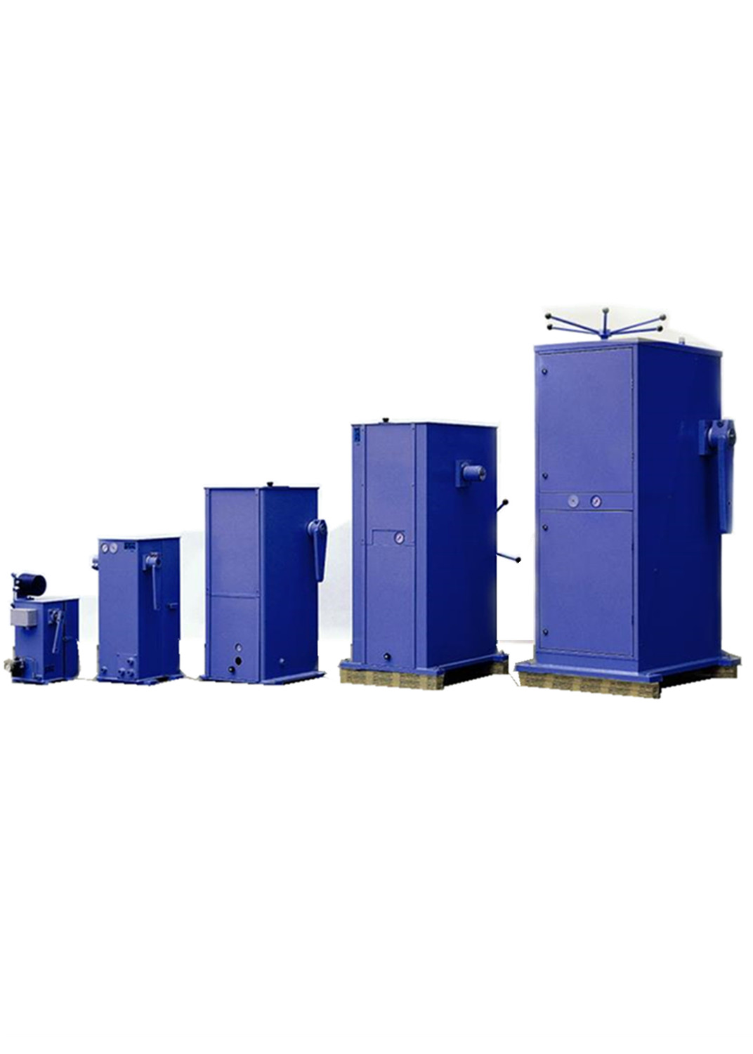
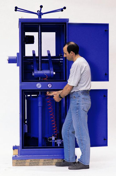
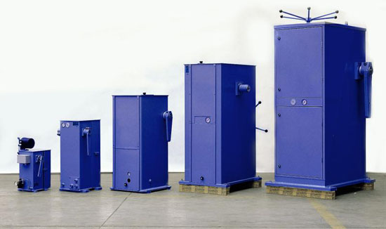
The TC series consists of cylinder, actuator control accessories and manual device, manual device integrated in the box shell, the steel shell to support and protection, to ensure continuous operation of equipment in harsh environments.
The regulating type actuator transfers the electric signals to the positioner, and controls the pressure of the two ends of the cylinder by the positioner, so as to realize the function of adjusting the opening of the torque device through the electric signal.
The switch type actuating mechanism controls the electromagnetic valve to gain electricity and loses the electricity, controls the cylinder both ends to enter the gas the direction transformation, realizes through the gain electricity and loses the electricity to control the torque equipment the switch function.
With the increasing capacity of modern power plant units, terminal components are required
The control moment (damper, fan, etc.) is also increasing, which is often required
The actuator can achieve more than 20000Nm by torque Look faster.
TC series pneumatic actuator fully meets these requirements:
Pneumatic actuators with various sizes (maximum cylinder diameter 520mm) are suitable
Different torque should be given; proper accessory design as well as pneumatic circuit can be formed Enough to guarantee fast response time.
TC series of actuators with the gas lock system, to ensure high
Degree of security in case of emergency. When the gas source is faulty, the gas is out of order
The lock activation is automatically engaged with manual operation, and it realizes the position before the fault
Mechanical locking.
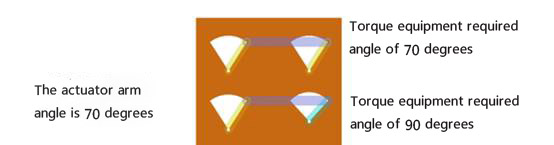
Platform installation and anchor bolt fixing The shaft end is provided with an output rocker arm, and both ends of the shaft are splined structures The initial position and direction of the whole rocker arm Two output angles, 90 degrees and 70 degrees
Solid box structure (all made of steel plate) The box has two functions: protection and support The space in the box can ensure the correct installation of the actuator and various accessories
The actuator is SC series cylinder actuator, with CDG patented permanent lubrication system, within the service life (30 years), do not need refueling removable panels, convenient maintenance and maintenance
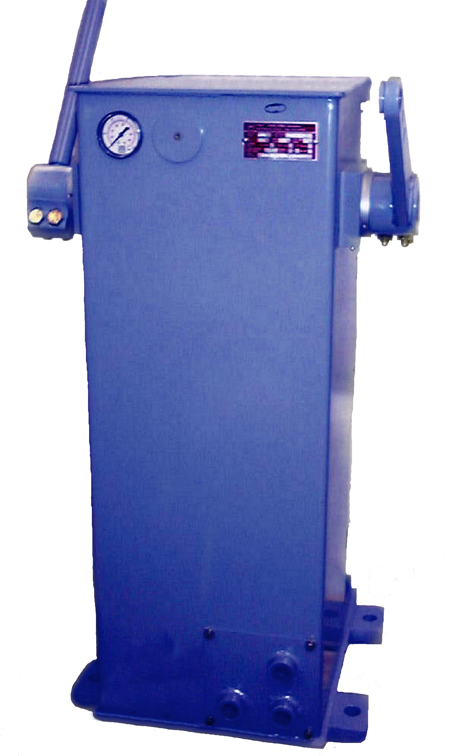
Enclosure:
-Locator: TZID-C1/4 '(ABB intelligent) other (user requirements)
-Position feedback -stroke switch
-Latching valve -solenoid valve
-Air filtration pressure reducing valve -Electric heater
-Pressure gauge -Pressure switch
-Spherical hinge
application:
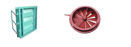
Widely used in electric power, steel, petrochemical and other industries, the actuator can control all kinds of valves, converter torque torque transmission and play equipment, this mechanism can be a certain distance through the connecting rod, making it more convenient in use and installation.
Angle selection :
Working principle:
Pneumatic pressure switch connected with air lock valve (D) when the gas source is lost
Lost air source, spring reset operation, two sets of three-way valve to air pipe locking
The position of the actuator keeps the gas source out of position. At the same time, air lock
The device can send out the "state signal" which is out of breath as a general monitoring or participation
Logical control of system.
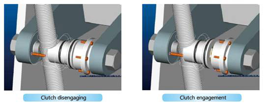
When the three way reversing valve (MC) is automatically controlled, the manual position is controlled at the connection position
When the clutch is in the closed position; gas separation, gas engagement. When system
When the gas source is lost, the clutch is meshed automatically with the handwheel mechanism. Therefore, the whole
All of the systems are locked mechanically before the gas is lost.
If manual control is carried out by hand wheel, the bypass valve (BP) should be opened
The cylinder is connected to the lower chamber and the cylinder is in free motion.
In addition, it is recommended to switch the three way reversing valve after the pneumatic lock (D) action
(MC) to the closed position, to ensure the stable engagement of the clutch, to prevent the gas source
Recovery misoperation.
Switching from manual control to automatic control
When manually switching to automatic control, remember not to build
Position deviation for switching. It is only recommended by the terminal adjustment mechanism
When the torque is transferred to the pneumatic actuator ahead of time, the clutch is disengaged
Unperturbed switching.
CDG designs this system and has a patent on it, and this system can be used in the system
Operation under the condition of maximum reliability.
When the gas pressure is restored, the air lock device is automatically reactivated, so the air lock device is automatically reactivated,
By closing the bypass (BP), the actuator can operate freely. Slow through
The control signal corresponding to the preset position of the terminal regulating mechanism is slowly reduced
In order to ensure that the actuator can fully bear by the terminal adjustment mechanism generated
Condition of moment. Under this balance condition, there is no load on the handwheel mechanism,
Switch the three way reversing valve (MC) to the connecting position, and the clutch is the same as the handwheel mechanism
Disengage and revert to automatic control state.
Manual device :
The manual device of the box type actuating mechanism uses hand wheel to drive the lead screw to rotate, and controls the power arm to move up and down. The disengagement and engagement of the manual device is controlled by a cylinder with spring reset, and the gas is disengaged and meshed. Note: when the air loss action, the manual reversing valve should be switched to manual position, to prevent the gas source suddenly restore false action. Detailed operation, see explanation.
The torque is referenced to the operating angle of 70 degrees, and this angle is the TC series Standard output angle of middle rocker arm. The angle of 70 degrees is considered to be the best one Effective control of baffle, butterfly valve and other terminal adjustment mechanism angle. Therefore build Do not exceed this angle when connected to the final control unit.
Only for the switching actuator, it is recommended that the terminal adjustment mechanism be used With a larger operating angle of 80 or 90 degrees. In general, according to what you want It is suggested that the maximum force distance is higher than the actual required force distance 50% to 100%, thus ensuring the operability of the actuator, and also
It can avoid the influence of gas pressure drop. In addition, if the actuator is equipped with the locking mechanism in the final positionIt is necessary to determine the setting point pressure of the air lock higher than that of the air lock device
Ensure the required torque limit pressure 10-20%.
Type selection table:
|
Executive mechanism
|
Theoretical value (Nm) of damper with damper
|
travel time
|
weight
|
|
Model
|
Rocker arm output angle
|
70°
|
90°
|
|
Bore / stroke
|
Minimum
|
Maximum
|
Minimum
|
Maximum
|
routine
|
fast
|
Kg
|
|
TC 63/125
|
90
|
117
|
142
|
83
|
117
|
0.5
|
…
|
30
|
|
TC 100/100
|
90
|
258
|
317
|
183
|
258
|
1.5
|
1
|
37
|
|
TC 100/200
|
70
|
517
|
633
|
358
|
508
|
3
|
2
|
103
|
|
TC 125/200
|
70
|
817
|
1000
|
575
|
808
|
3.8
|
2.5
|
108
|
|
TC 125/250
|
70
|
1014
|
1239
|
717
|
1007
|
2.5
|
|
153
|
|
TC 160/200
|
70
|
1341
|
1638
|
942
|
1333
|
3
|
|
163
|
|
TC 160/300
|
70
|
2007
|
2464
|
1413
|
2000
|
4.5
|
2
|
260
|
|
TC 200/300
|
70
|
3174
|
3891
|
2239
|
3159
|
7
|
3.5
|
280
|
|
TC 260/300
|
70
|
5399
|
6616
|
3804
|
5377
|
12
|
6
|
305
|
|
TC 260/400
|
70
|
7196
|
8819
|
5072
|
7167
|
16
|
8
|
520
|
|
TC 330/400
|
70
|
11790
|
14442
|
8304
|
11739
|
|
13
|
620
|
|
TC 390/450
|
70
|
19090
|
23370
|
13160
|
18810
|
|
30
|
1550
|
|
TC 420/450
|
70
|
20464
|
24551
|
14116
|
19957
|
|
36
|
1600
|
|
TC 520/450
|
70
|
33610
|
41190
|
23320
|
33140
|
|
45
|
1700
|
|
control accuracy
|
≤0.5%
|
|
Air Pressure Request
|
Dry clean instrument air
|
|
Filter pressure reducing valve
|
5 um
|
|
Gas pressure
|
0.25~0.7Mpa,0.25~0.6Mpa(Intelligentpositioner)
|
|
Ambient temperature range
|
G1/2, G3/4 ( Special customizable )
|
|
Interface dimensions of electrical apparatus
|
1/2 GF,3/4 GF Optional
|
|
Air source interface size
|
~80℃ Standard (-40℃ ~150℃ Optional B10 )
|
|
Output angle
|
0° ~60°、0°~70°。0°~90°
|
|
Command signal input
|
4~20 mA
|
|
Position transmitter output
|
4~20 mA
|
|
Solenoid valve voltage
|
DC 24 V
|
|
Positioner
|
DVC6200、6DR5110 Or customer requirements
|
|
Limit switch
|
DC 24 V Mechanical or non-contact type
|
|
Protection grade of actuator
|
IP 66
|
|
Joint and pipeline
|
Nickel plating on copper 、 Stainless steel
|
|
Paint
|
Carbon steel sprayed epoxy resin
|
Texture of materia:
|
Part name
|
Texture of materia
|
Part name
|
Texture of materia
|
|
Box
|
Carbon steel spraying
|
Cylinder
|
63-125,Aluminium alloy/160-300 carbon steel
|
|
Output arm
|
Carbon steel spraying
|
Piston rod
|
Chrome
|
|
principal axis
|
Alloy steel38NiCrMo4 heat treatment
|
Cylinder piston
|
Aluminium alloy
|
|
Screw
|
Alloy steel38NiCrMo4 heat treatment
|
base
|
Carbon steel spraying
|
|
Axle sleeve
|
Aluminium bronze
|
rocker arm
|
Carbon steel spraying
|
|
Handwheel piston
|
Aluminium bronze
|
Spherical hinge
|
Alloy steel
|
|
Clutch
|
3Cr13
|
Compound bearing
|
304+PTFE
|
|
Actuator type
|
Hinge type (rocker arm dimension)
|
Inner diameter of connecting rod - Recommended wall thickness
|
|
TC 63/125-100/100
|
Φ16-12
|
DN30->6
|
|
TC 100/200-125/200
|
Φ16-15
|
DN30->6
|
|
TC 125/250-160/200
|
Φ20-20
|
DN30->6
|
|
TC 160/300-200/300-260/300
|
Φ25-20
|
DN53->8
|
|
TC 260/400-330/400
|
Φ30-30
|
DN53->8
|
|
TC 390/450-420/450-520/450
|
Φ45-40
|
DN69->10
|
|
|
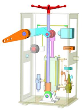
Actuator structure diagram
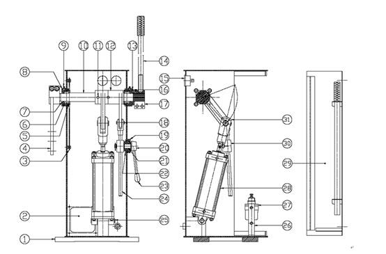
TC 63/125-100/100-100/200-125/200
|
Serial number
|
Name
|
|
1
|
Lock
|
|
2
|
Back door board
|
|
3
|
Internal leverage
|
|
4
|
Worm screw
|
|
5
|
interface board
|
|
6
|
Positioner
|
|
7
|
Shim
|
|
8
|
Pressure gauge for working gas source
|
|
9
|
Pneumatic actuator
|
|
10
|
Cylinder base
|
|
11
|
Filter
|
|
12
|
Box main body
|
|
13
|
Shaft end connection
|
|
14
|
Dial
|
|
15
|
principal axis
|
|
16
|
Axle pin
|
|
17
|
Limit ring
|
|
18
|
Spherical bearing connection
|
|
19
|
rocker arm
|
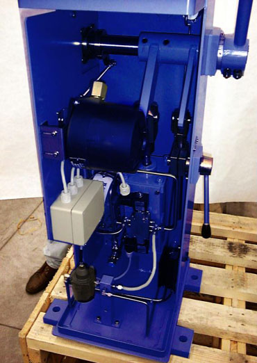
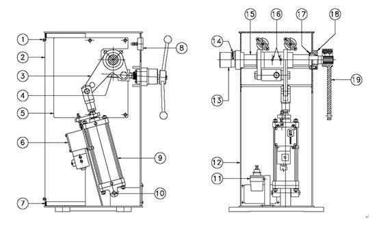
TC 160/300-200/300-260/300
TC 260/400-330/400
TC 390/450-420/450-520/450
|
Serial number
|
Name
|
Serial number
|
Name
|
|
1
|
Box frame
|
16
|
Ring
|
|
2
|
pin
|
17
|
Back door board
|
|
3
|
Bush
|
18
|
Bearing
|
|
4
|
Front fixing plate
|
19
|
Positioner
|
|
5
|
Inner sleeve
|
20
|
Pneumatic actuator
|
|
6
|
axis
|
21
|
Cylinder base
|
|
7
|
Front door board
|
22
|
pin
|
|
8
|
Manual switch
|
23
|
Wire rod base
|
|
9
|
Signal source pressure gauge
|
24
|
pin
|
|
10
|
Lock
|
25
|
Articulated device
|
|
11
|
Pressure gauge for working gas source
|
26
|
Hand wheel connecting rod
|
|
12
|
Top opening
|
27
|
Mechanical locking device
|
|
13
|
handwheel
|
28
|
Pointer
|
|
14
|
rocker arm
|
29
|
Dial
|
|
15
|
Washer
|
|
|
|
NO
|
Name
|
NO
|
Name
|
|
1
|
base
|
16
|
Indicator board
|
|
2
|
interface board
|
17
|
Manual control junction
|
|
3
|
Liner
|
18
|
U shape clip
|
|
4
|
rocker arm
|
19
|
Locking end block
|
|
5
|
Internal leverage
|
20
|
Locking pin shaft
|
|
6
|
Spherical bearing
|
21
|
Seal ring
|
|
7
|
Dust ring
|
22
|
screw
|
|
8
|
Bearing sleeve
|
23
|
Locking lever
|
|
9
|
Oil standard
|
24
|
Locking shaft
|
|
10
|
axis
|
25
|
Cylinder support
|
|
11
|
Elastic pin
|
26
|
Gas separation support
|
|
12
|
Spindle sleeve
|
27
|
Filter
|
|
13
|
Dial
|
28
|
Cylinder
|
|
14
|
Manual lever
|
29
|
door
|
|
15
|
Pressure gauge for working gas source
|
30
|
Guide block
|
|
|
|
31
|
U shape clip
|
TC 125/250-160/200

|
